01 / MATERIAL OPTIONS
Materials
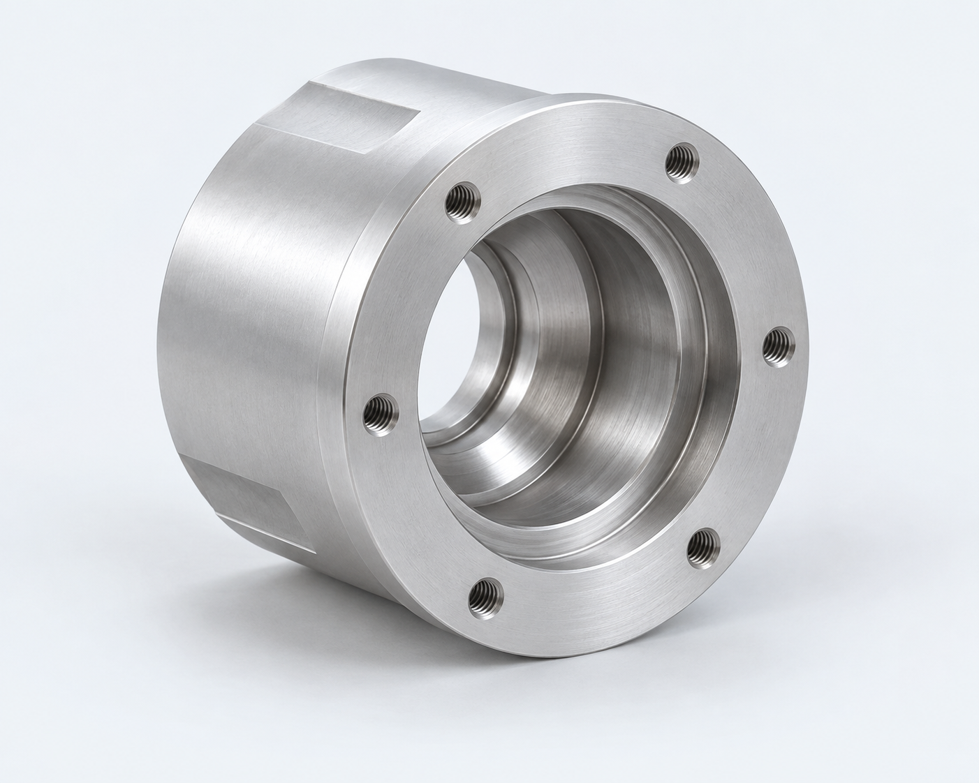 COMPONENT ILLUSTRATION
6061 Aluminum
Specify the material grade, temper and finish requirements with your drawing.
Grade & temperFinish requirements

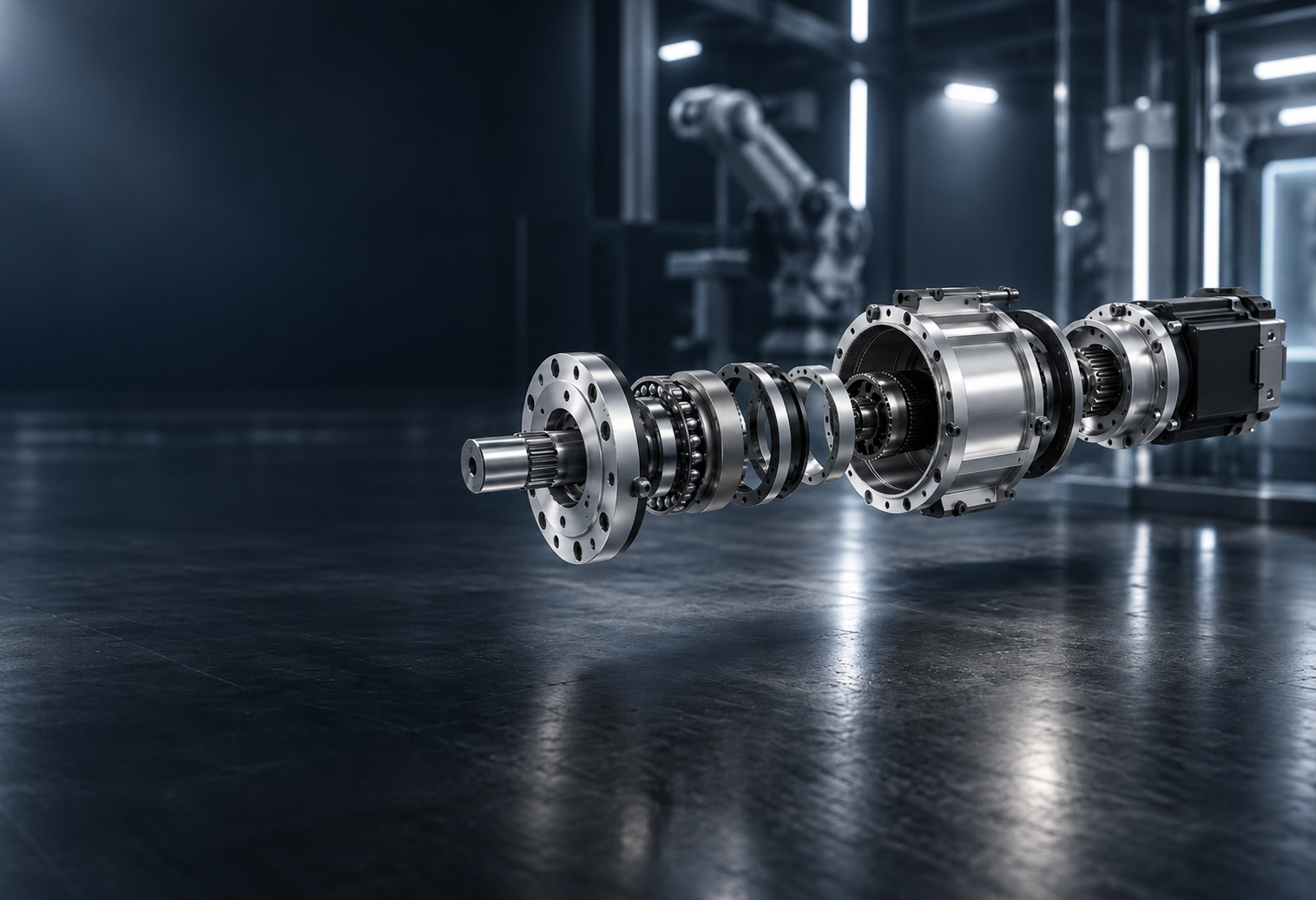
M-Lathe manufactures precision CNC machined components for robot joint actuators, including actuator housings, shafts, bearing carriers, output flanges and motor / gearbox interface parts.
CRITICAL INTERFACES / HOUSING STUDY
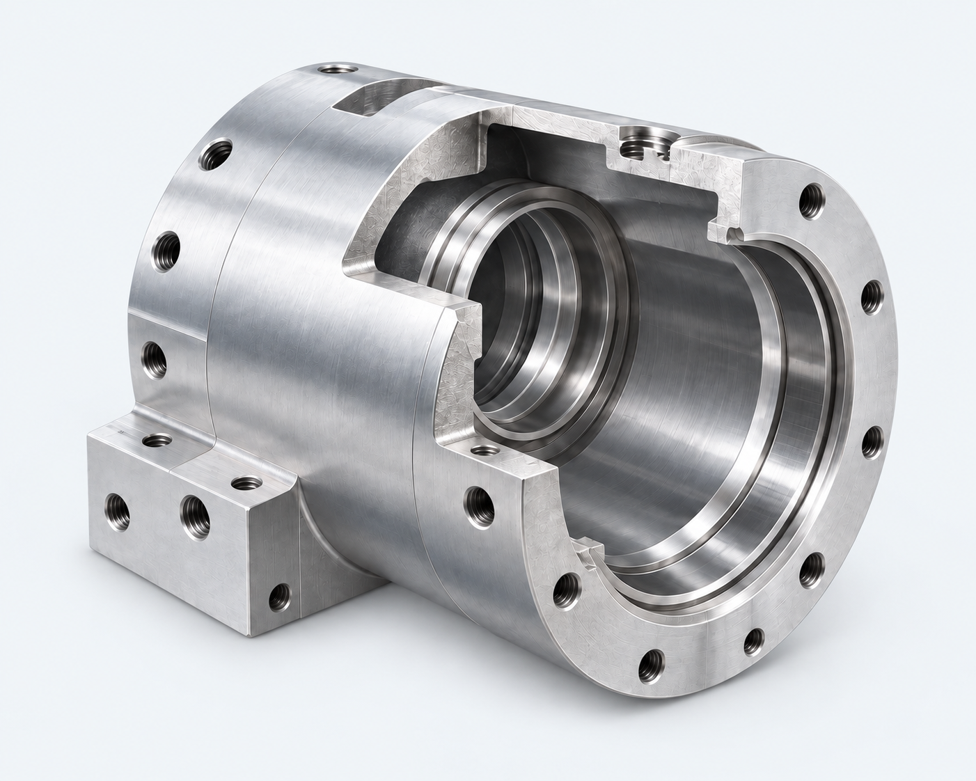
Review relationships between coaxial features.
Illustrative geometry · Drawing-specific requirements05 / BATCH CONSISTENCY
Repeated illustrations represent a production sequence.ENGINEERED AROUND YOUR DRAWING
Focused machining and inspection planning for the interfaces that matter.
Review internal bores and outside diameters relative to the specified datum axis. Your drawing defines the required geometric controls.
Review the relative position and alignment of bearing seats, together with the drawing’s assembly and inspection requirements.
Define bearing-seat fits and assembly clearances from the mating components, operating conditions and drawing requirements.
Identify the reference faces and axes used to locate critical features during machining and inspection.
Plan consistent setups and inspection of critical features across prototypes and production batches.
Specify finish requirements for bearing seats, seal interfaces and mating faces according to their function.
Opens your email app. Attach your drawing before sending.
FROM MATERIAL TO FINISHED PART
Explore material and process options for your actuator components.
COMPONENT ILLUSTRATIONSpecify the material grade, temper and finish requirements with your drawing.
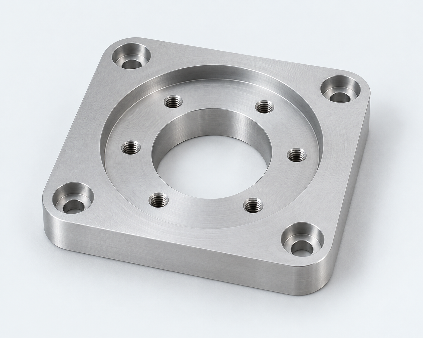 COMPONENT ILLUSTRATION
Review turned diameters, bores, shoulders and end-face features against your drawing.
Have a material or finish requirement?
Selected: 6061 Aluminum / CNC Turning
Images illustrate component geometry, not specific alloys or finishes. Material and process suitability are reviewed against your drawing.
QUALITY & INSPECTION
Drawing-led inspection for the features that matter.
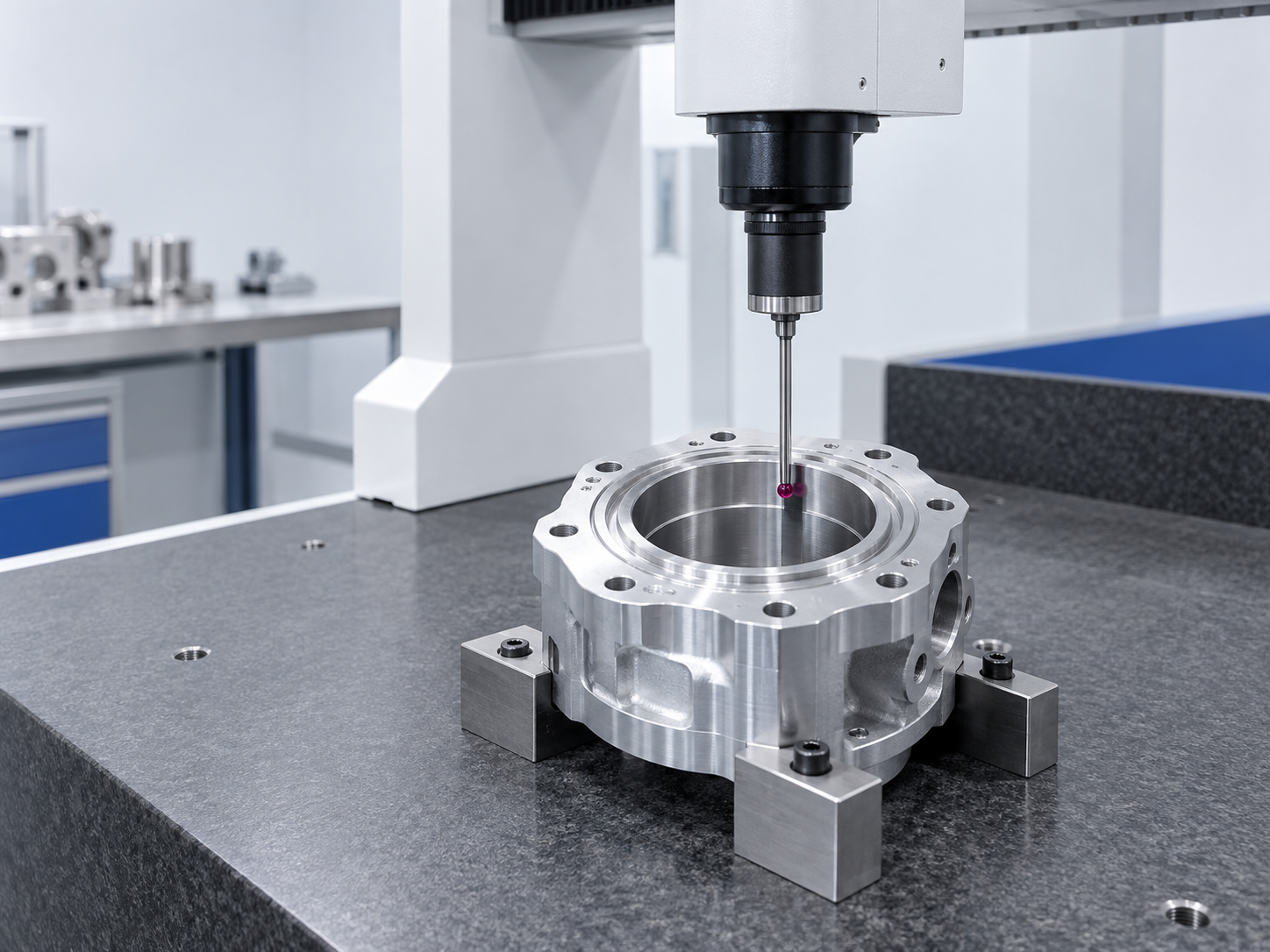
Review critical bore locations, datum relationships and mounting features against your drawing.
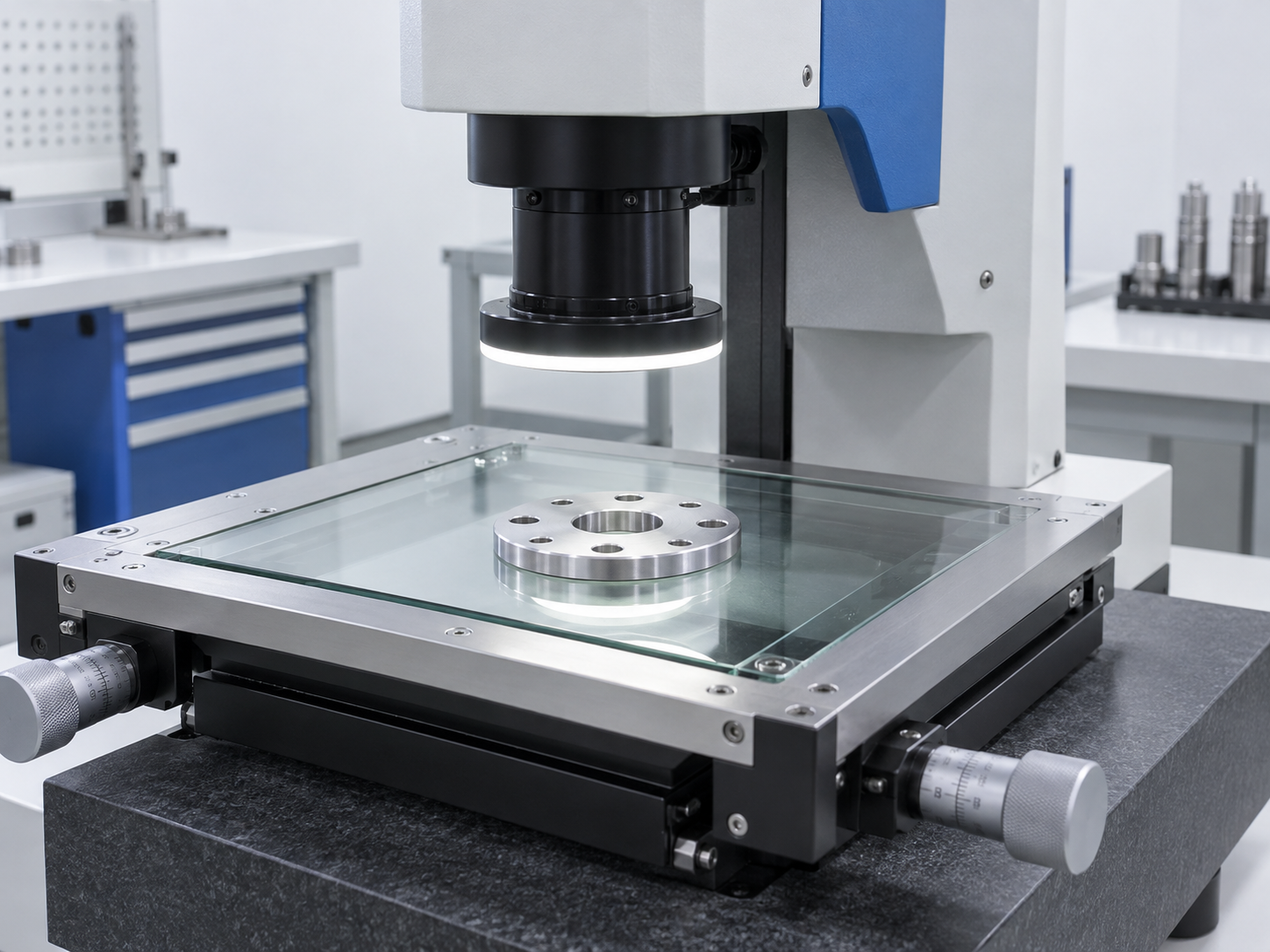
Discuss non-contact checks for visible profiles, hole patterns and accessible edges. The inspection method depends on feature visibility and drawing requirements.
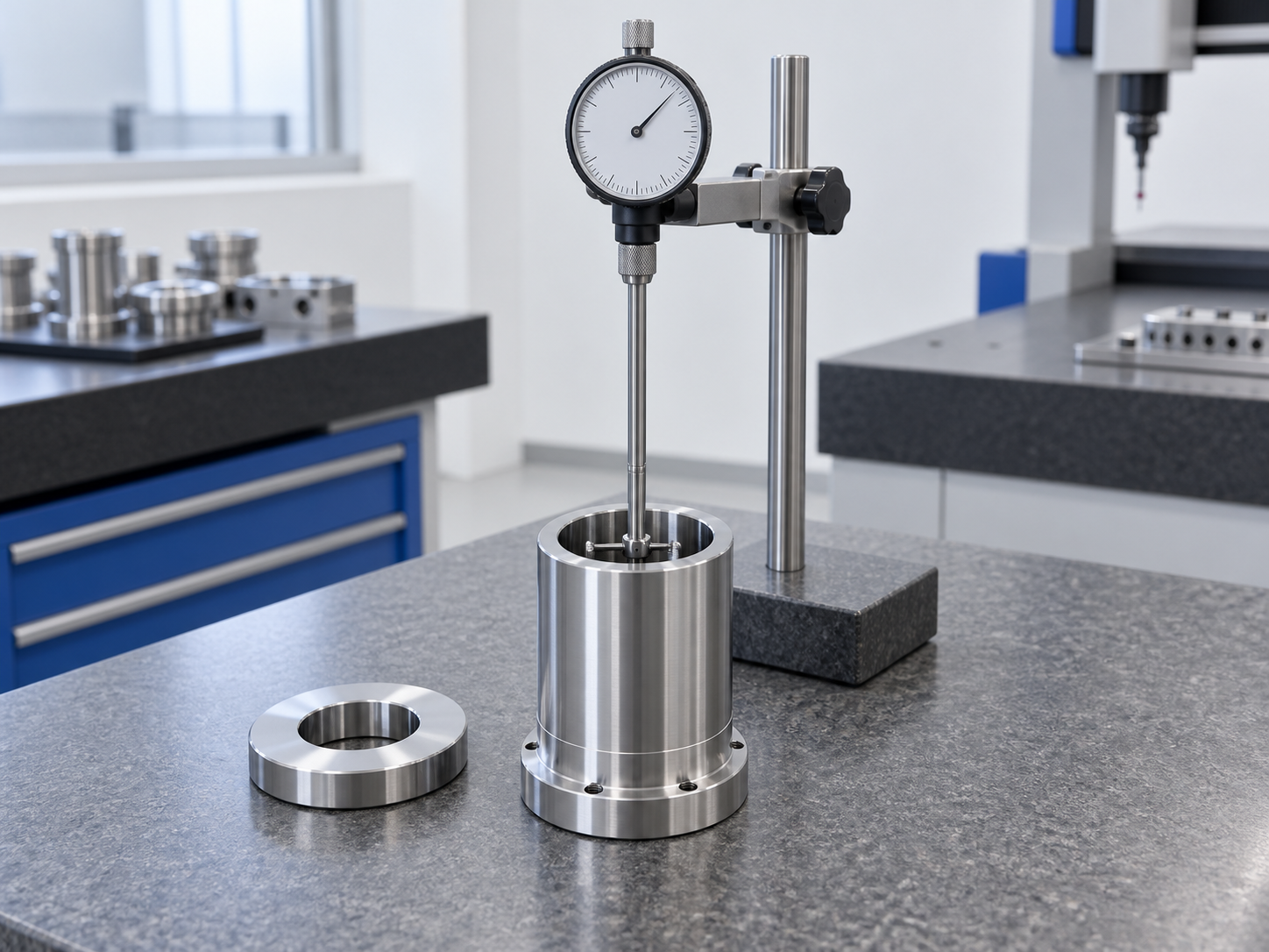
Plan checks for specified bore sizes and fit-related dimensions using suitable gauges. Gauge selection and acceptance criteria follow the drawing.
Share your drawing and critical features with our team. Inspection scope is subject to review.
APPLICATION EXPLORER
Explore where custom actuator components can fit into your design.

Select a joint marker to explore its interfaces.
01 / 06 · APPLICATION
Explore machined interfaces for compact, multi-joint robot assemblies.
AI-generated application concepts. Markers illustrate possible interface areas, not internal construction or customer projects.